
TEMPERATURE COMPENSATED PIEZOELECTRIC CRYSTAL OSCILLATOR GK367 GK367-UTK-04
Temperature compensated piezoelectric crystal oscillator GK367-UTK-04 manufactured as per KPGF.433531.074 TU, SMD7 package
Basic parameters
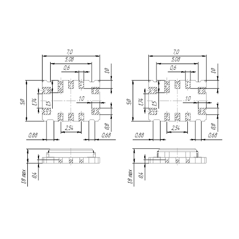
Number and pin assignment
Overrall dimensions
Appearance


Model identification code: GK367-UTK-04-AG-30М-3.3С-B KPGF.433531.074 TU
| Oscillator type | GK367-UTK-04 |
| Operating temperature range | А |
| Temperature instability of frequency within operating temperature range | G |
| Nominal frequency, MHz | 30М |
| Supply voltage, V | 3,3 |
| Output wave form (S – Clipped Sine, CMOS – no sign) | С |
| Relative frequency change | B |
Electrical parameter
| Parameter | Value |
| Nominal frequency range, MHz | 5 - 64 |
| Adjustment accuracy, х10-6 | ± 1 |
| Frequency tuning, х10-6, min | ± (5…20)* |
| Control voltage, V: | 1.65±0.01 |
| Output parameters: | |
| wave form | Clipped Sin |
| Peak-to-peak voltage, V, min. | 0,8 |
| Spectral density of phase noise at 10 kHz offset, dB/Hz, max. | -130 |
| wave form | CMOS |
| Logic ‘1’, V min. | 0,9 Us |
| Logic ‘0’, V max. | 0,1 Us |
| Pulse ratio, % max. | 50 ± 5 |
| Rise/fall time, ns, max: | 3 |
| Supply voltage, V | 2,7 ± 5 %; 3,0 ± 5 %; 3,3 ± 5 %; 5,0 ± 5 %; |
| Output voltage vs. load deviation ±20 %, ×10-6, max. | ± 5 |
| Load coefficient ± 20 %, ×10-6, max. | ± 0,2 |
| Load capacitance: | |
| Clipped Sine | 10±20% kOhm, 10±20% pF |
| CMOS | 15±20% pF |
| Supply current (Clipped Sine), mA | 1 - 4 |
| Supply current (CMOS), mA | 4 - 24 |
Impact resistance to external factors action
| Parameter | Value |
| Mechanical impact resistance | М6 Group, GOST 25467 |
| Climatic impact resistance | UKhL 2.1 cat., GOST 25467 |
| Leak-proof construction | |
| γ-percentile time to failure at γ = 95 % under standard operating conditions (at ambient temperature of 85 °С) for min. 20 000 h within 15 years of service life. | |
| γ-percentile storageability time – min. 15 years with γ = 95 %. |
Notes:
1. * - To be specified depending on nominal frequency. 2. Specifications can be modified to meet Customer’s specific requirements.
Fractional frequency change
| Configuration | Fractional frequency change, ×10-6, max. | ||
| 1st year of operation | Operating lifetime | Storage | |
| А | ± 0,5 | ± 2,0 | ± 2,0 |
| B | ± 1,0 | ± 3,0 | ± 3,0 |
| No sign | ± 3,0 | ± 5,0 | ± 5,0 |
Temperature instability of frequency within operating temperature range, х10-6
| Operating temperature range, ˚С | Temperature instability of frequency within operating temperature range, х10-6 | |||||||
| ±0,3 (V3) |
±0,5 (G) |
±1,0 (D) |
±1,5 (G1) |
±2,0 (D1) |
±2,5 (E) |
±3,0 (E1) |
±5,0 (Zh) |
|
| 0…+50 (L) | + | + | + | + | + | + | + | + |
| 0…+70 (К) | + | + | + | + | + | + | + | + |
| -10…+60 (А) | + | + | + | + | + | + | + | + |
| -30…+60 (Е) | + | + | + | + | + | + | + | + |
| -30…+70 (P) | + | + | + | + | + | + | + | + |
| -30…+85 (R) | + | + | + | + | + | + | + | + |
| -40…+70 (B) | + | + | + | + | + | + | + | + |
| -40…+85 (S) | + | + | + | + | + | + | + | + |
| -60…+85 (G) | - | - | - | - | - | - | - | + |
Piezoelectric oscillator


